This course is a quick-fire set of video tutorials to get ICEM Surf A-class users up and running in Alias as quickly as possible. Once you’ve mastered the interface and the differences in terminology – which aren’t that different TBH – you’ll find that surfacing is pretty much the same in both systems. There are a couple of major differences in Alias – 1) Alias has history and 2) Alias was designed from the beginning to be NURBS based. Some A-class modellers – and CAS modellers come to that – don’t use either – which I think means they’re missing out on some of Alias’s advantages, although I can see it makes life simpler. You definitely want to try out history and NURBS before deciding. I don’t use NURBS for major blocks very much – but certainly for things like fillets – just like you can in ICEM Surf of course.
In this course I want to try and get you working in Alias as quickly as possible. Your knowledge of patch planning etc is still 100% relevant in Alias and therefore I will focus only on how the functions work and where the methodology is different to ICEM Surf. Alias has a huge number of functions. We don’t need to go into detail on all of them. If I leave out any functions it’s because I don’t see any use for them in A-class work or they’ve been superseded by other options.
We’re not going to cover non-A-class topics such as SubD, rendering or animation. I’ll teach you enough about rendering to enable you to shade your models with appropriate materials and in an environment. If you really want to do high quality renderings then VRed is a better option.
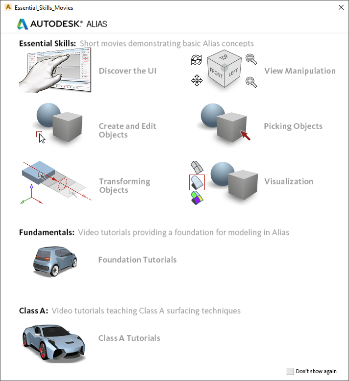
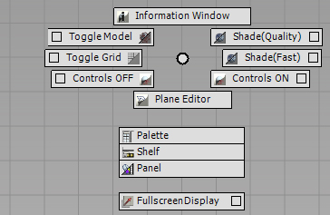
Once inside Alias you will get this menu:
These are a very good set of tutorials which are a great introduction to Alias. If you close this down now don’t worry – you can get it back by picking Help-Essential Skills from the top menu bar.
When we created the sphere it was at an arbitrary point in space. If we wanted to position it at a specific location then we could specify an exact position using the User Prompt. To get into the user prompt window we can either click there or, more easily, pick Tab. Then we need to input XYZ values separated by spaces or commas.
To create a sphere on the XZ plane at an arbitrary location then we go to the LEFT view. Make sure that you’re in orthographic mode. If you can’t see the grid then you’re in Perspective mode.
Then we can insert a sphere wherever we want. If you rotate into FRONT view you’ll see that the sphere is on the XZ plane. In an orthographic view such as FRONT we can also snap spheres to the grid points using Alt+MB1.
Whenever we create an object you can see that it’s highlighted. In other words it’s in selected mode. If we use Alt+L you’ll notice that it zooms into the selected object. Delete deletes the currently selected object. What if we want to select more than one object?
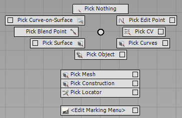
Selection of objects is under the Pick tab on the Palette. Pick Object is how we select objects. Notice that in the very top corner of Alias it shows the current function at all times. So Pick Object is now active until we pick another function. To pick objects we can either use single picks or drag a window. All 3 mouse buttons can be used for different types of picking.
MB1 adds objects to the selection – but if they’re already selected then it deselects them.
MB2 only ever adds to the selection – regardless of whether they’re already picked or not.
MB3 only ever removes objects from the selection.
To deselect all objects we use Pick Nothing. This is a very useful function and you will find yourself using it constantly.
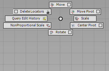
To move an object we can use the Move function under the Transform tab. Firstly we need to select the objects that we want to move.
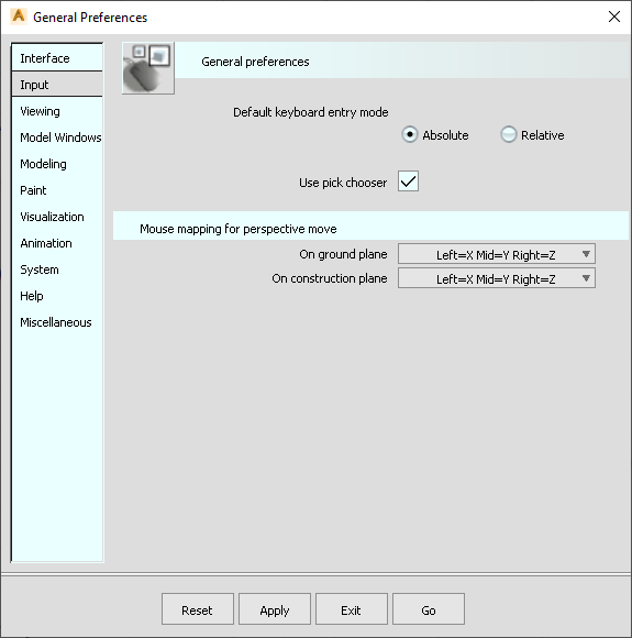
Next we need to check that the behaviour of the movements is specified correctly in the General Preferences function. We want to map the mouse buttons to the X, Y and Z directions. In other words, MB1 will move the selected objects in the X direction when we’re in the Perspective view – strictly speaking for us it’s the orthographic view but everyone talks about the perspective view. Similarly MB2 moves objects in Y and MB3 moves objects in Z.
If we go into an orthographic view such as LEFT the object moves differently though. Now MB1 allows us to move the objects freely, MB2 moves them left to right – the X of the screen – while MB3 moves them up and down – the Y of the screen.
The Rotate icon rotates the objects. The MB1 rotates about X, MB2 about Y and MB3 for Z. it doesn’t matter what view we’re in. Notice that the rotation is about a local Pivot point which is shown in green.
Scale will scale the objects using the MB1. Again, scaling takes place about the local pivot point.
As you’ve seen the pivot point is critical when we’re rotating or scaling an object. If we want to move it we use Move Pivot and then specify a location – such as the origin – using either Alt+MB1 or specifying XYZ values of 0 0 0. Now when we rotate the object it rotates about the origin.
Most curves are created with the CV Curve option under the Curves tab. CVs are control vertices – exactly the same as the control points in ICEM. The CV Curve function lets us input the CVs directly. Notice that this function has a square symbol in the corner. This means that if we double pick it a menu opens. These are the settings that I recommend for now. I will explain these in detail at a later stage.
If we want to create a curve on the XZ plane we would go into the LEFT view. Input as many CVs as you want. Once you’ve created the shape that you want then you can either pick Next Curve or – more easily – the space bar. Now you can input more curves if you want – or you can stop.
Just as in ICEM we can modify curves – and surfaces - using the CVs. One way is to select the CVs using Pick CV and then any of the transform functions such as Move, Rotate and Scale. By positioning the pivot point in different places we can get some interesting effects. The other way to move CVs is to use the MoveCV function. To access this we have to pick the icon and then hold the space bar down. To move CVs in X, Y or Z we pick the top symbol – XYZ – single point and then the Move symbol. We’ll set the Mouse Sensitivity – which is the equivalent of Mouse Warp – to 1 so that we can see the movements easily. To undo any movement we use Ctrl-Z. You can do multiple Undos with Ctrl-Z in many – but not all functions. Hurrah!
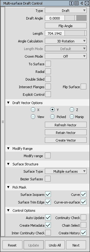
Now we’re going to create a draft surface using MSDraft under the Surfaces tab. MS just means multi-surface. MSDraft is very much the same as Flanges in ICEM. Double clicking the icon opens the full menu. We want a draft surface – or flange – in the Y direction so we’ll select Draft with zero draft angle and the Draft Vector Y. At the bottom of the menu we’ll put Auto Update and Create History on. The User Prompt is asking us to pick a curve or curves. To pick one curve we simply select it – or if we want more than curve then we can drag a window over them. Let’s get rid of the draft surfaces by picking Undo All. The other way we can use the function is to select the curves first and then go into the MSDraft function. To create a single surface on both sides we tick on Double Sided and Single Surface. Because we have Auto Update on we immediately see the result.
The surfaces that we’ve just created have history on. You should be able to see a subtly different colour which indicates history. So if we pull CVs around on the curves then the surfaces change. This can be incredibly useful – but there are also times when we don’t want history. In which case we can delete it using Delete Construction History. This means that we can now pull CVs on the surfaces – using Move or MoveCV – just like we did with curves.
In ICEM Surf we have Faces. Rather confusingly for ICEM users, in Alias, a Face is called a Trimmed surface. The equivalent in Alias of an ICEM Trimmed surface is a Trim Converted surface.
Creating a Trim Converted surface in Alias is a two-step process. Firstly we have to make a Trimmed surface – or Face in ICEM. Then we convert it to a Trim Converted surface – in other words a Trimmed surface in ICEM.
[DIAGRAM]
Suppose we wanted to trim this surface to this curve, projected in the Z direction. Firstly we project the curve onto the surface to create what’s called a Curve on Surface or COS. A Curve on Surface is attached to the surface always. If we modify the surface or the curve then the COS moves with it. In this case we have History on so the Curve on Surface is constantly updated. To trim the surface we simply pick the Trim Surface function and specify the part of the surface that we want to keep. This is exactly the same as Face in ICEM. The difference here is that we can still modify the surface using the CVs.
If we wanted to create a Trim Converted surface from this surface we use the Trim Convert function and simply pick the Trimmed surface. We’ll put Keep Originals on here so that we can compare the Trimmed and Trim Converted surfaces. Trim Convert in Alias is equivalent to Trim in ICEM.
The visualization tools in Alias can give you really good images. These were state of the art in their day. But these days VRED is a better option for high-end visualization. Apart from being more powerful it is just so much easier to use. But it’s worth learning some of the vis tools in Alias for everyday use. To shade models there are various options but for now we’re just going to use the hardware shading. We can switch on the Ground Plane to get shadows on the floor if we want. If we click on Edit Environment we can make the shadows blurred.
Surface colours are called Shaders in Alias as opposed to Materials. To access these we have to change the Workflow to Visualize. The surfaces that we’ve created have the default shader. It’s best to leave the default shader as it is. If we wanted to change the colour of an object then we should make a copy of the default shader. If we double-click this then we can change the name and alter the characteristics of the shader. We can change all sorts of properties of a shader including textures, reflections, bump maps etc. But I really wouldn’t bother with these unless you like making things very complex. There are predefined shaders which make this sort of thing easier – or, if you really want great renders then use VRED. We will cover some basics here though. The first thing is the Shading Model. PHONG and LAMBERT give fairly matt results. BLINN is for shiny objects. Colour is the main material colour. Specular controls the colour of highlights and the sliders below control the nature of the specularity. It’s best to experiment with these to see what they do. Diffuse effectively adds a room light to the model so that the darker areas are lighter. We’ll ignore Reflectivity for now.
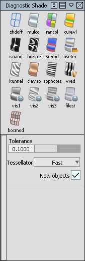
Another way of shading a model is to use the icons in the Diagnostic Shader. Shade Off is wireframe, Mulcol shades the selected surfaces or everything if nothing is selected.
Alias uses layers rather than Lists to organize the data. No doubt you’ve encountered layers in other systems. Whereas Lists are like a filter to the complete database which means that you can see the same objects in more than one List, Layers contain the data. In other words an object can only be in one Layer. If you wanted the object in another layer as well you would have to make a copy of it – which is not recommended by the way. Later on we’ll look at Categories which allow you to group layers together and give you the same benefits as Lists.
The layer bar shows all the layers. The Default Layer is where objects get put unless you tell the system otherwise. To create a layer use Layer-New. Notice that the last layer created is highlighted in yellow. This means it’s the active layer. Any new geometry will be put on this layer. To change the active layer just click on the one that you want. To assign geometry to a layer pick the object and then Assign. To toggle the visibility of a layer click on the box. To pick all the objects on a layer use Pick Objects.
You’ll find most of the tools to analyse the geometry under the Locators and Evaluate tabs. Other analysis functions are in the Diagnostic Shading window.
A lot of the File options are self-explanatory. It worth pointing out that there are lots of data types that Alias can handle, such as IGES and STEP or course, but it will also read and write out ICEM EDF and CATIA V5 files.
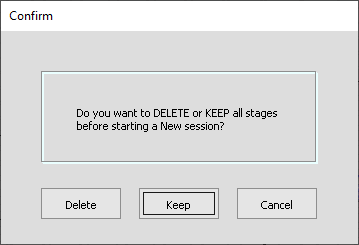
One thing that Alias can do is have multiple files open at the same time. These files are then called Stages. A group of Stages is called a Stage Set. For instance, if we have a file open and then want to create a second file we simple pick File New. We’ll then get this menu:
If we say Delete then the current database is closed - it’s not deleted as such unless we haven’t saved it in which case it will be lost. Keep means we’ll keep it open. Cancel means we’ve changed our minds about creating a new file.
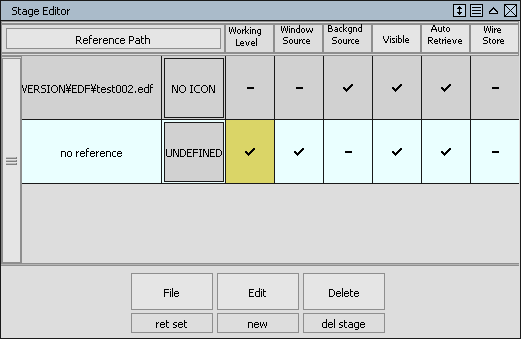
If we’ve pressed Keep we’ll then have two files open. These are now called Stages. To see these we click on the Stages where there is a list of the Stages. To get more detail we can click on Edit. This opens a window like this:
Each row details information about that stage or file. The new file doesn’t have a name at the moment. This is the Working Level. In other words the file that we’re working in. You’ll notice that at the moment we can also see objects from the other file, but in a light green colour. If you don’t want to see these then tick off Visible for the other file. If you tick off visible for the new file it makes no difference at the moment. It’s usually best to turn all Visible ticks off [USE PULLDOWN FROM TOP OF COLUMN] and then when we change the Working Level we never get the background objects from other files shown.
If you want to remove a file from the Stages then select it and then Delete Stage. Delete is slightly misleading - it’s only removing it from this Stage Set, not deleting the data from the disk.
You can save Stage Sets if you want from the File menu.
Another way to have two files open is to open two sessions of Alias. I do this if I’m working on one file but have another, more complete version ready for the design management when they unexpectedly pop round and want to see the latest model. If you do this all in on Stage Set then there’s more chance of Alias crashing just before they arrive!
Before you change the interface you might want to export the default preferences first just in case you want to get back to them. I would suggest saving these as PrefSet DEFAULT FACTORY SETTINGS.aps. Then export again to PrefSet.aps. This will be the file that is overwritten as you change the menu settings.
This makes it easy to go back to the default settings [USE MENU NEXT TO USER PROMPT] if you needed to.
If you really want to safeguard the original preferences then you can do this by copying the whole preferences folder to somewhere else on the system. The preferences folder should be in C:\Users\Admin\AppData\Roaming\Autodesk\Alias\. For Alias 2021 the folder will be UserPrefs2021. Make a copy of this - UserPrefs2021-BACKUP for instance.
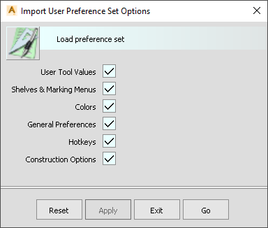
The user preferences include all the menu positions, user defined shelf, hotkeys etc – basically any changes you’ve made to the interface are stored in the user preferences. You can see what is being saved if you go to the Import User Preferences menu.
I would recommend getting used to where the functions are in the default menus before you add too much customization.
The user can customize the interface to exactly how they want it. Once you’ve got the menus and settings as you want you need to save these as your user preferences. Then you can save this. The next time you open Alias you’ll find your menus and settings exactly as you left them. Alternatively you can Export your preferences which may be useful if you wanted different preferences for different ways of working. You can then Import them when you want them. [EASIEST WAY TO ACCESS PREFS IS FROM BAR NEXT TO USER PROMPT]
To alter the general layout go to Preferences Interface Palette/Shelf Layout.
Windows is where you can open or close the Palette, Shelf and Control Panel. The Diagnostic Shading window can be opened or closed under Object Display.
As an example let’s open the Surfaces tab and then increase the height of the window using the double arrow. Some of the icons in the Palette have a little square symbol in the corner. This means that a double-click will open a menu. A single click just goes straight to function with the settings as they are. If there is a yellow arrow in the corner then this means that there is a set of icons here.
The windows can be moved and resized by picking on the window edges. The little arrow minimizes the window. If the window is not big enough to show all the open tabs then a slider appears.
Widening the palette means you get more icons per row and therefore a shorter window. Some people prefer to orient the palette horizontally.
If you open up some of the drop down menus from the top line you’ll see that there are hotkeys defined already for some functions. For example File Save As is Alt+s.
I’m going to start with setting up hotkeys because there are some that are so useful that we ought to set them up now. To edit the hotkeys we go to Preferences Interface Hotkeys/Menu Editor. Here you can specify a hotkey for virtually anything! The tabs correspond to various parts of the system. Menu refers to the top menu bar.
The first hotkey I think we should put in is for saving the user preferences as we will be doing this a lot when we start to customize the menus.
There is a safeguard when you exit Alias if you’ve not saved your preferences but I wouldn’t take the risk! So we go to Menu Preferences and type Ctrl+p in the box next to Save Preferences. Now Ctrl+p will save any changes that you’ve made to the menu. The menu doesn’t differentiate between upper and lower case characters. If you type in lower case it’ll just revert to capitals when you press Apply.
The other hotkey that I think is essential for File-Save. Every other system has this as Ctrl+s whereas Alias doesn’t! To set it we simply open up the File tab and write Ctrl+s in the box.
Other hotkeys we’re going to set up now are for opening and closing windows. This is under Windows. We’ll set them to Shift+p, s and c. You may sometimes find that the hotkeys that you want to use are already allocated to something else. If it’s a function that you’re not likely to use then overwriting it is no problem.
One other hotkey that we’ll set for now is Hardware Shading. We’ll make this s. By default this is assigned to Special Paint Size which we’re not going to need.
A tool that is incredibly useful for looking at all sorts of data is the Information Window. This is something that I use all the time and so I’ve assigned the hotkey “i” to it.
Now we Apply to finish. You can test out the hotkeys – for instance Shift+p should open and close the Palette. What about s? It should toggle the shading of surfaces but when we press it nothing happens. The reason is that, by default, single hotkeys don’t work. To get them working we have to click Preferences Interface Toggl Single Hotkeys. We only need to do this once and now s should work.
We’ll add more hotkeys later but these’ll do for now. Don’t forget to use Alt+P to save the preferences so far!
|
|
We can drag any functions onto the User Shelf using the middle mouse button. These can be functions from the Palette, the top menu bar, the Control Panel or the Diagnostic Shade window. If you pick an icon with a yellow arrow then you’re actually dragging all of the icons in the set. If you only want one icon then make sure you pick on that rather than the whole group. If you want to get rid of an icon on the shelf then just drag it into the bin.
With the shelf we can specify multiple copies of the same functions, each with different settings. For instance, suppose we wanted to create 2 versions of MSDraft for surfaces in the Y and Z directions. We drag MSDraft to the shelf twice. Then we modify the first one to have Y set. The second one will be with Z set. So that we remember which is which we can use Ctrl and double-click on the icon to rename it. Only lower case, spaces and underscore are allowed. If you try anything else it will change it for you.
If you want to separate icons you can add blanks and other symbols using Preferences Interface Shelf Extras.
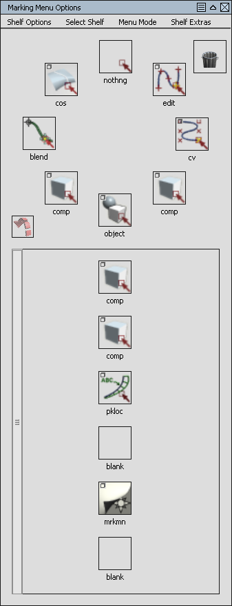
The Marking Menu is really useful. It’s accessed by pressing Shift+Ctrl and one of the mouse buttons. It pops up at the cursor. The menu depends on which mouse button you’ve picked. By default:
MB1: Selection
MB2: Transform
MB3: Graphics, Menus etc
If you let go of the mouse button while hovering over a function then that function is activated. If you let go of the mouse button while hovering over a box then that menu will be opened.
You can customize the marking menu using Preferences-Interface-Marking Menu. This is for MB1 at the moment:
Just as we did for the shelves we can just drag a function with the middle mouse button to any of the locations on the marking menu. If you now open the marking menu using Shift+Ctrl+MB1 then you’ll see the change. The name of the function will be in full. To make this easier to read you can edit it using Ctrl+double click and changing the Title.
Don’t forget to use Alt+P to save your preferences!
[NEED TO COMPARE ICEM AND ALIAS HOTKEYS – COME UP WITH A GOOD SET]
To toggle the grid display go to Window Display – Toggles – Grid.
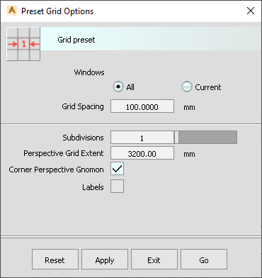
To change the grid parameters go to Construction Preset:
Here you can control the grid spacing and the extent of the grid. This is the distance in each direction from the origin. By default the grid extends from -3200 to +3200 in each direction.
Defining the Grid Spacing as 1000 and subdivisions to 10 is nice if you want to see clearly where the 1m divisions are.
Planes and vectors are construction entities. Like geometry objects then can be placed on layers. The Plane Editor can switch to chosen planes and toggle visibility. I would rather put planes and vectors in layers and hide them that way. This is much easier if you have 3 planes to switch off and on. Usually planes are relevant to only certain parts of geometry and so it makes sense for them to be in the same layer.
By default we are in World Space. By selecting a Plane we are then in Global Space.
[VIDEO]
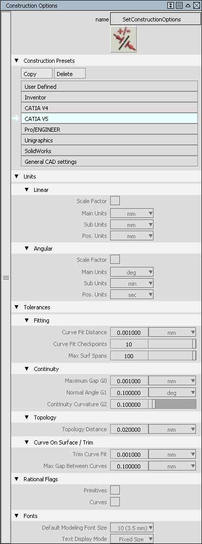
Unlike ICEM where we specify the required position, tangency etc when we check our model at the end, Alias works in reverse. We set up our tolerances right at the beginning. This has the advantage that we can check continuity etc throughout the development of the surface model. So at the end there should not be any surprises.
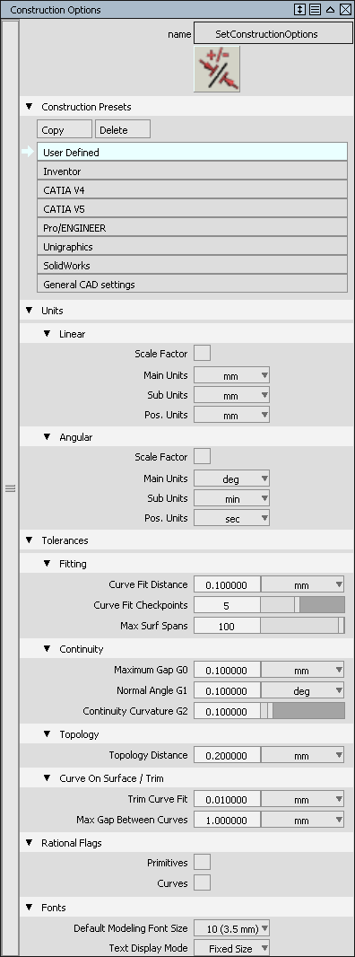
This is the default menu with all the tabs opened. In the first section we have a number of presets which define values in the menus below. If we pick Catia V5 for instance we get:
This shows all the settings but they are greyed out. What we can do though is take the Catia V5 settings as a starting point and then edit them if we make a Copy. We can change the name to something appropriate - such as A-class. The settings are automatically saved as we change them - there is no save button in this menu.
As an ICEM Surfer you’ll no doubt want to leave the Linear units as mm.
In the Fitting section the Curve Fit Distance is how the system decides whether two points coincide or not. For example, there is surface creation function called Square which allows you to create a surface from 4 curves - just like Patch Create Curves. By the way it doesn’t create square surfaces! It’s just the name of the functions. Slightly misleading I know! If the curves don’t quite meet at the corners then it won’t put a surface in. It’s the Curve Fit Distance that determines this. If we make the distance large then Square will be much more tolerant of errors between the curves. This is great for CAS work - but not a good idea for A-class. When we put in a Square surface we really want the system to tell us that the curves aren’t joined properly. So I would suggest either keeping Curve Fit Distance as 0.001mm or maybe slightly smaller.
Curve Fit Checkpoints determines how many points are used when analysing the continuity between surface edges. It also affects the accuracy when trimming surfaces to curves. The default is 10 which is far too small for A-class. Ideally we want it as large as possible. The slider doesn’t go any further than 10 - but you can type in 100 which is the maximum value allowed.
Max spans determines the maximum number of NURBS segments when surfaces are created. I’ll explain NURBS in detail later. For A-class work we always want the minimum number of spans. Some users insist on sticking to 1 which is the same as Bezier. The default values is 100 which is far too high for anyone. But it doesn’t matter too much as we always control the number of spans when we build surfaces - and curves.
The Continuity settings are pretty much the same as in ICEM Surf. Alias refers to G0 for position, G1 for tangency and G2 for curvature. G3 is the same in both systems although there is no value for this in the Construction Settings. I set G0 to 0.0009mm, G1 to 0.05 degrees - which is 3 minutes and I leave G2 as 0.1.
Topology Distance has exactly the same meaning as in ICEM Surf. It determines whether two edges should be analysed for continuity or not. Any two edges which are further apart than the Topology Distance will be assumed to be free edges. Usually I set this to 0.5mm - but for very small geometry it may need to be smaller than this.
Trim Curve Fit is the maximum allowable distance between a COS (curve-on-surface) and the trim edge. Max. Gap determines whether two COSs actually join.
We only put on the Rational flags if we’re creating rational geometry. I’ll cover this in detail later on - but actually we shouldn’t ever use this type of geometry so we’ll leave the flags unticked.
The Draw Precision affects how facetted curves and surfaces appear. You can find this under Object Display or the Control Panel Quality tab. 0 gives the most facetted display - 1 gives the best quality. You’d always want this set to 1 unless your machine was slow or the model was very large.
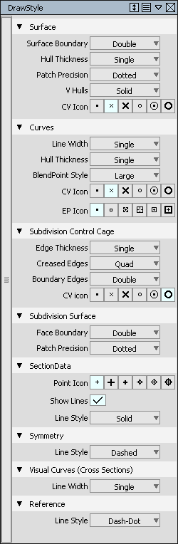
Draw Style is equivalent to the Display menu in ICEM. The settings apply whether objects are selected or not, unlike ICEM.
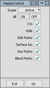
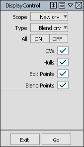
The Object Display Control menu determines how objects will be displayed.
Active applies to all selected objects when you pick Go. So picking Active and ALL ON would result in all selected objects having CVs, Hulls etc on.
If the Scope is ALL then everything is affected. With New Crv, New Srf etc the chosen settings are applied to any new geometry. As we’re doing A-class work we nearly always want everything visible so that we can immediately see any problems with the CVs and so forth.
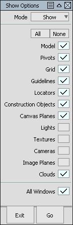
Window Display Show lets us select what is visible.
Model turns all edges and curves on and off. Notice that Pivots is in this list. We usually want Pivots on all the time.
Construction Objects are Plane, Vectors and Points. Locators are diagnostic displays.
Windows Display Toggles has exactly the same list of options and is usually the easier place to go for these. You’ll notice that Model - the toggle for edges and curves - is assigned to the hotkey F12 which is really useful. If you’re in shaded mode you’ll find that F12 is very handy for seeing the model without the wireframe.
If you need to bring in background images then, in ICEM Surf you would use Background or an Environment Box which needs Magic or the Real Time Rendering Licences. This functionality is included in Alias Concept and Autostudio but not Surface.
To read in an image - for example a vehicle side view - firstly go to the orthographic view that you want. Then go to File-Import-Canvas Image but pick on the box. Tick the Always Create New Canvas option. Then every image that you bring in can be moved around separately.
You can pick the image as an object and then move it around or scale it. When it comes to positioning it correctly first move the pivot point to a distinct location - such as the centre of a wheel. Then move the image so this point is in the right place. Then scale the image.
If you want to create curves over it then you can dim the image using the Canvas Layer Editor. Now the curves will be easier to see.
There is an alternative to Canvas Images which is Image Plane. I don’t find this useful as it doesn’t move with the view. If you accidentally create one - which everyone does at some time - then you’ll probably be puzzled about how to delete it as you can’t pick it as an object. You have to use Pick-Image which is in the Pick-COS slideout by default.
So far we’ve only picked entities as Objects. An Object can be a group of entities. For example with MSDraft, if we select several curves we get a group of surfaces. You can see when we pick Object on any of these surfaces then the whole group is selected. The same thing happens with the Flange function in ICEM - this puts all of the patches created into a single group.
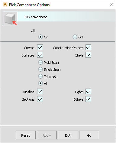
What if we wanted to pick only one surface? Remember that in Alias a surface is a single entity - not a group of entities as in ICEM. Then we would use Pick Component instead. By default Pick Component picks any of these entities:
Curves are individual curve entities.
Surfaces are individual surfaces. Notice that there are options to be more specific about the type of surface.
Construction Objects are planes, vectors and points.
Shells are a type of object created by Boolean operations on surfaces - which we’ll cover later.
Mesh is the term used in Alias for scan data.
Sections, lights and Other are fairly obvious.
You can use the default settings - where every type of entity can be picked - as is if there are no other entities nearby. But if you want to be specific about what you’re picking then you have to switch off the things you don’t want. Rather than do this every time it makes sense to save variants of this menu.
If you go to the Marking Menu you’ll find under the MB1 options that this has already been done for you to some extent. Here you have Pick Curves, Surfaces, Mesh and Construction Objects. If you want to add any other variations on this you can by customising the Marking Menu. Personally I think Pick Component with everything on is a useful addition.
Other entities that can be picked include:
Templates. Templating is a way of temporarily making an object visible but unpickable. This is a very useful function. All you have to do is pick an object or component then press Ctrl+T to turn it into a template. To turn it back again you have to use Pick Template and then Ctrl+T will toggle it back to its pickable state.
Pick COS is for picking curves on surface.
Pick All picks everything - including Templates.
Pick Locators picks all diagnostic objects - another thing we’ll look at later.
Alt Grid points
Ctrl End points of curves, CVs, Edit Points
Ctrl+Alt Slide along a curve or edge
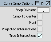
Can permanently put these on. There are also curve snap options:
There are so many ways of organising data in Alias that it is almost bewildering. I’m sure that ever Alias modeller will have a different way of doing this. As long as they are in control of their own data then maybe it doesn’t matter so much. It’s obviously a different matter if you have to share models. Obviously you can have your own take on data management within your WIP model and a company standard approach when you send data to someone else.
At the simplest level I would imagine that everyone uses Layers. Layers are nice and simple and they transfer into other systems like ICEM Surf and Catia with no problem. Other types of division won’t. For transfer between Alias users it may be that there are departmental standards that have to be met. If in doubt a simple set of layers is always going to be best.
The options for dividing and viewing the data include:
My criteria for choosing a way of handling my own data includes:
I don’t tend to use the Reference Manager - but then I didn’t in ICEM. If machine performance was an issue or I was having to manage data rather than surface I would use it.
In the early stages of developing a model I will tend to use only the Layers. I might use the Layer Folders as well while the model is small. When it gets larger then I’ll start to use Categories especially when it comes to managing different versions of the same data. When I’ve got a finalised model then I will put the data into Groups that correspond to the physical components. For instance if I had a bumper I might have one Group for the main moulding and another for the grille. As a way of structuring the data and checking for position continuity then Shells are a good option.
I use the Object Lister for some functions. For looking at Groups in Alias I still use the SBD window - which is not the most user friendly menu but it gives a great visual take on how objects are grouped together.
Layers are the main way of dividing up the data in Alias. Unlike Lists objects can only exist in one layer at a time. If you want List-like behaviour then you can do this using Categories. These point to Layers rather than individual entities but they behave in a very similar way. I’ll explain Categories in a few minutes.
The first thing to do is to Toggle Layer Bar. Now we can see the layers easily. At the moment we only have the Default Layer. We can create new layers using Layer New. You’ll notice that the last layer created is always highlighted in yellow. This means that it is the active layer - in other words any objects created now will be put onto this layer.
To change the active layer just click on the layer name. To change the name double click it.
To move objects into a layer we pick the objects or components first and then assign them. To toggle the visibility of the layer we click on the box. Pick Objects picks all the objects on this layer.
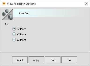
Symmetry with Layers is like the F8 Display Mirror function in ICEM Surf. By default Symmetry refers to the Y0 plane. But we can change this to any Plane that we want. We select the Layer that we want and then we Select the Plane that we want to use. Then switch on Symmetry for the Layer. If the symmetry plane is Y0 then we can use the vwflp which is like F7 in ICEM Surf and vwboth which is like F8 in ICEM. These affect all of the geometry, not just that in the current Layer.
The options apply only to the World Axes.
The layer can be made Pickable, Reference or Inactive. Pickable is just the default state. Reference means that we can’t pick the object but we can reference locations on it. Inactive means that we can see it but not select it or reference it in any way. I’ve never felt the need to use Inactive. Templates are pretty much the same and are easier to use I feel.
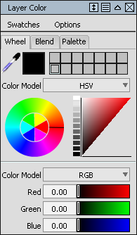
To change the colour of a layer click and hold the box. You can either select one of the preset colours or create your own.
To delete a layer use Layers Delete Selected Layers. To delete all the layers that are not being used then pick Layers Delete Unused Layers.
When you’re creating objects there’s two ways of doing this. Either you put all new objects on the Default Layer and then assign them to the create layer or you pick the layer that you want in order to make it active and then create the geometry.
If you Save As a model as an ICEM EDF then by default you’ll find that each layer corresponds to a PART in ICEM which makes data transfer between the two systems pretty streamlined.
If you have lots of layers then a slide bar will appear below them which makes it easy to access the hidden ones. But if you have say 30 layers then the slider becomes very tedious.
The Layer Menu is a good way of dealing with larger numbers of Layers. To access the layer menu go to Windows Information Layer Stats. This makes it a lot easier to handle lots of layers. To order the layers in name order for example you can Select All [FROM THE TOP] and then click at the top of the Layers column. Or if you wanted to make all layers invisible you can tick off visibility of one of the layers. You can’t pick on the Default Layer though as it is always visible. To pick only one layer just pick on it. To make a layer active double pick on the colour swatch. To change the name double pick on name.
Another way of looking at the layers is via the Object Lister [WINDOWS]. One feature of this that I find very useful is the ability to copy of a layer and all its contents. I use this if I need to create another version of a part - say I’ve been working on Grille V1 and now I want to do Grille V2.
The SBD Window is a way of looking at objects in terms of how they are grouped together. You can dynamically translate and scale the view in the same way as you can in the Graphics Window. SBD stands for Scene Block Diagram. It’s not very user friendly but I think it is the best way of getting an overview of the data and especially understanding what is happening when you Group and Ungroup objects.
Categories are like Lists for Layers. I find these incredibly useful for handling large datasets. By default there are two categories: Uncategorized and Selected Layers. Uncategorized is a list of the layers that are not in a user defined Category.
To create a new category pick Category New. To delete a Category pick the Category and then Category Delete. To add Layers to a Category you can drag them, using the middle mouse button, from the Uncategorized Layers.
To change a Category name double click on it. Click on the square to toggle the visibility. To remove a layer from a Category you can right click over the layer and Remove from Category. To show only the Category layers in the layer bar then right click over the Category and click Listing. To see only the layers in the category, use Isolate. To see everything again then Show All [TOP LINE].
Another way of including Layers in a Category is to drag them from the Object Lister. I find this much easier when you have lots of layers when it becomes difficult to have the Uncategorized tab open and still see the current Category. I find this really useful when I want to make a new version of a part. Say we have a layer called Wing Mirror V1 and we want to make a copy of this called Wing Mirror V2. The easiest way to do this is with the Object Lister. The right mouse menu lets us Duplicate Layers and Contents. We can rename this.
We might want the first version in a Category called ASSEMBLY A, along with other parts. We want the second version in ASSEMBLY B. We can drag all the Layers that we need from the first Category into the second. Then we can drag the V2 layer from the Object Lister.
There is a Reference Manager in Alias which is similar to that in ICEM Surf.
Sometimes it’s useful to add some comments to an object. Maybe to explain which planes to use for the tool direction or what the draft angle is. Edit Comment is under Object Edit. It simply opens a text window where you can type and save text. To interrogate an object for comments pick the icon and then click on the object. Or you use Query Edit and then right click on the object.
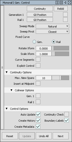
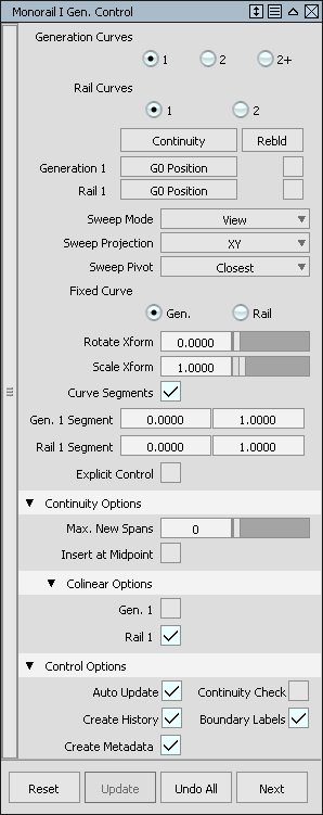
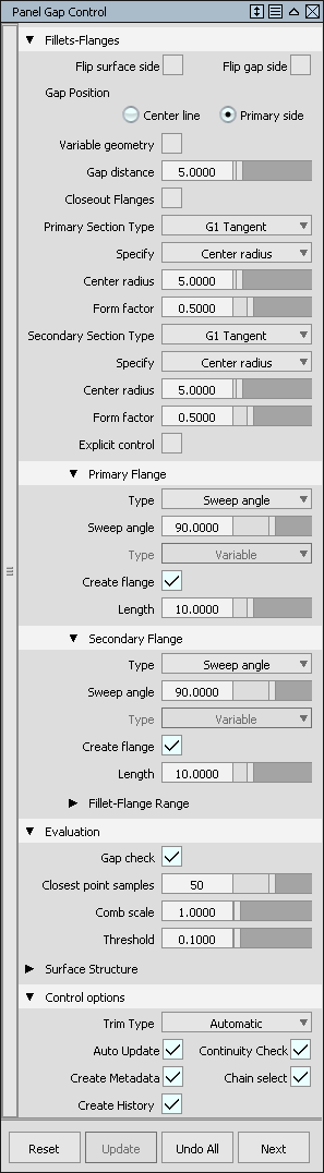
We’ve seen how you can put History on in a function. As an example let’s look at the Rail function which is similar to the ICEM Surf Profiles function to some extent. The simplest option is to create a rail surface using a single Generation Curve - the same as a Profile in ICEM - and single Rail curve - the same as the Spine in ICEM Surf.
We want to put Auto Update on so that any changes in the settings are immediately reflected in the surfaces. Create History means exactly that. Create Metadata means that the system will store the menu settings, even if History was off.
Once we’ve created the surface we can edit the CVs of the Generation Curve and the Spine and see the surfaces update. Notice that the surfaces with history are a different colour to surfaces without history.
If we’ve come out of the Rail function but now want to modify the menu settings again then all we have to do is pick Query Edit and then the geometry. This opens up the menu again. Now we can change the settings.
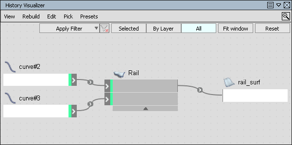
If you want to see the History in detail then open the History Visualizer. By clicking on the elements here we can see which objects are which. We could then replace one of the curves with a new one for instance.
Sometimes History can become a problem. I usually find History is great for initially setting up the surfaces but then, as the project develops, history may become too cumbersome to maintain or it can cause really unexpected problems. So we need to be able to delete the history when necessary. Some users never use History, which means they’re missing out on one of the benefits of Alias. I’ve also seen new users, especially ones who’ve come from a parametric system such as Catia, try to keep History on everything. It’s just not a good idea.
To delete History on selected objects use Delete Construction History or Ctrl+Alt+H.
If you want to get rid of a set of objects that have history on then, rather than delete them, it’s often more efficient to Query Edit them and then Undo All.
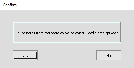
If you’ve deleted History you can still recover the settings if you had Create Metadata on when you created the object. You can’t activate the history with Query Edit, but if you pick Query Edit and then the Object with the right mouse you’ll see which function was used to create the object [RESULT OF]. In this case it’s Rail Surface. Alternatively the Information Window will show this as well. Now if you pick the function - in other words Rail Surface - then you’ll get this menu:
Answer Yes and the Rail Surface menu will pop up with the settings as you used when you created the surface. You can then delete the old surface, pick the curves again and you’ve got a surface with History on again.
If you want to get rid of the Metadata you can delete it [DELETE CONSTRUCTION METADATA].
Explicit
Create History - usually at bottom of menu - one exception is Trim Surface
Space Bar - to access menu buttons bottom right of screen
Colinear - surface menus
Rebld - uses parameterisation from other curves
Auto Update - usually this should be on all of the time. The only time I would turn this off is in the surface fillet functions when the surface can take a long time to update. It’s then worth turning off Auto Update while you alter the settings.
Chain Select - great for picking connected curves. It’s very like the Chain function in ICEM Surf.
Continuity Check - can be to the parent surfaces but may also apply to internal edges.
In a lot of menus to complete the function you have to pick the menu at the far bottom right of the graphics window or press the Space Bar. In some cases there are multiple buttons there. It’s the selected one that is activated by the Space Bar.
The other place to look always is the User Prompt to guide you through the menu selections.
For surface functions there is often a Multiple or Single Surface option. For Multiple you can choose Bezier. Usually this gives the very best result in terms of simplicity.
Both ICEM Surf and Alias support Bezier and NURBS. There may be ICEM Surf users who’ve never used NURBS though in which case I will try and explain the differences.
Bezier geometry in Alias is exactly the same as in ICEM in that we use controls to move the geometry. The difference is one of terminology. In Alias we call the controls Control Vertices or CVS. The other terminology difference is that Alias refers to the degree of a curve or surface as opposed to the order. In the case of a Bezier curve for example the degree is simply on less than the order. Or you can say that the number of CVs is one more than the degree.
The lines that connect the CVs are the hulls.
In early CAD systems there were different mathematical ways of defining geometry. So there might be a Bezier algorithm for freeform surfaces but a cylinder algorithm for cylinders and a box algorithm for boxes. If the system had to find the intersect between 2 Bezier surfaces then this would be another algorithm, the intersect between a Bezier surface and a cylinder would be another and so forth. So there would be a proliferation of algorithms for different combinations of geometry leading to a greater risk of software bugs. NUIRBS was created to try and fix this by having a unified approach to all geometry. Therefore there would only ever need to be a single intersect algorithm for instance.
NURBS stands for Non-Uniform Rational B-Splines. We’ll talk about the B-Spline bit first.
In ICEM Surf we’re used to building everything with Bezier. Of course, when we have to create a more complex shape then we have to match a series of curve segments or patches together. B-Splines are a way of joining Bezier curves and surfaces together. For now we’ll just talk about curves. In Alias a B-Spline curve is still controlled by Control Vertices, but it now has internal divisions called Edit Points. If you’ve ever built BSplines - or NURBS - in ICEM Surf then these are called knots. The area between the Edit Points is the span which, in ICEM Surf is called a Segment.
The number of CVs is now Degree+Number of Spans. If we only have one span then we have a Bezier curve.
If we convert a BSpline curve to Bezier then we get an exact result. [USE DETACH] Each span converts to a single Bezier curve.
When we create a Bezier curve we know that it is completely continuous. It’s not possible for there to be any jumps in the curvature for example. With BSplines then we do get limited continuity at the Edit Points. The nature of the discontinuity depends on the degree. To display curvature on curves we can use the Control Panel to specify Curvature U and then the Curvature icon to specify the settings - scale, min max and number of spikes to be sampled.
[VIDEO TO SHOW EFFECT]
From this we can say that if the degree of the BSpline curve is 3 or more than we have G2 curvature continuity everywhere. If the degree is 4 or more then we have G3 continuity everywhere.
BSplines allow us to create more complex curves. What they don’t let us do is represent conics exactly. Conics are any shapes that we can create by doing a planar cut on a cone. In other words, circles, ellipses etc. This is where Rational geometry comes in. Rational BSplines have CVs with not only X, Y and Z values but also weights. The weights allow us to modify the shape of the geometry.
In reality the user does not have to specify the weight values - the system does this for us. To create Rational Geometry we have to switch on the Rational Flags in the Construction Settings. Then we can create a NURBS based 90 degree arc for instance. We can do this with only 3 CVs. If we put the curvature min max values on and scale this up you can see that it’s 100% accurate. If we created a non-rational curve with the same CVs then we wouldn’t get an accurate result at all. The reason is that the middle CV has a weight that is not 1. If we look at the Bezier curve then the weights are all one. you can get some really extreme results if you edit the weights. I’m not suggesting do this in reality! It would not win you many friends. In fact, I would imagine that most companies would not want you to use Rational geometry at all.
I would turn off Rational Geometry now so that you don’t accidentally create any.
The Non-uniform aspect of NURBS refers to what is known as the Knot Vector. If we create a multi-span BSpline curve and then pick the Edit Points and look at them in the Information Window we can see the u-parameter value of each Edit Point. This list of Edit Point or knot parameter values is known as the knot vector. If the parameter values are irregular then the curve is Non-Uniform.
Strictly speaking Bezier curves are single span BSplines which are uniform non-rational NURBS. In other words BSplines are a special case of NURBS, but you will find that nobody talks about BSplines - they’ll just refer to NURBS when they’re talking about multi-span curves and surfaces. Bezier they might call Bezier but equally single span NURBS.
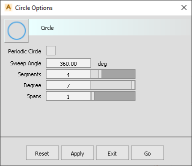
If we’re to avoid Rational geometry then we’ll have to approximate our arcs and circles. Fortunately, as in ICEM Surf, this is easy to do. We’ll start with the Circle function. These are the settings you should use:
This is for a full circle. Use 4 segments, NOT spans. This results in 4 separate Bezier curves which approximate a circle very accurately. [SWITCH ON MIN/MAX CURVATURES] Even if we scale up the circle enormously the radii are still accurate within 0.0009mm.
When you scale a circle the Absolute scale factor is the Diameter. So if you wanted a radius of 1000mm then the Scale factor would be twice this - in other words 2000.
As for ICEM Surf if you have very small circles or arcs then you can reduce the number of segments and the degree if you want - but just check that you’re still within a tolerance of 0.0009mm.
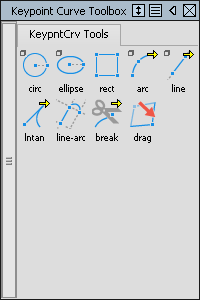
Another way in which you can create a circle is using the Keypoint curve menu but again, don’t use the default values!
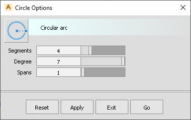
These should be the settings. The advantage of this menu is that you can specify a centre point and then a point on the circle to define the radius.
There is also a set of arc options here. Again, the degree should be 7 not 6 in order to get accurate results.
DON’T use the ellipse tool in the Keypoint Curve Toolbox. Try it and you’ll see why once you put the CVs on. Instead, create a circle in the usual way and then use Non-Proportional Scaling to create an ellipse.
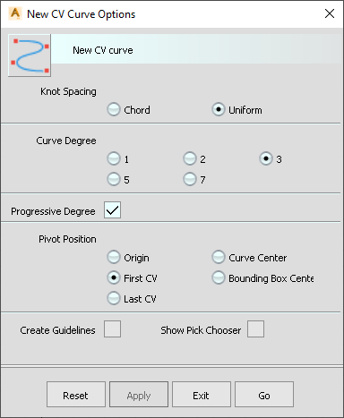
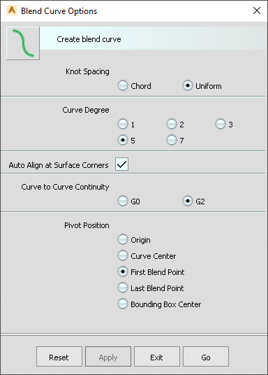
CV Curves are ones where we specify the positions of the CVs. Usually you’ll want to define these in an orthographic view.
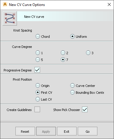
Let’s talk about the Knot Spacing first. By default this is set to Uniform and this should always be the case. There is no reason to change this and using Chord is positively a bad idea. To show why we’ll set Chord. Then we’ll define two multi-span curves with the same number of CVs. We can check the degree and number of spans in the Control Panel. If we then use Skin to create a surface between the curves we might expect a surface with the same degree and spans. The lines that we get across the surface are the isoparms or knot lines. You can see from the Control panel that we’ve got a lot more spans than we expected. Why is this? This is all down to using Chord when we created our curves. If we select all the Edit Points on the curves you can see that we don’t have regular knot parameter values - these are Non-Uniform knots. They are based on the arc length of the curve.
If we repeat this process with Uniform then you’ll see that we get a surface with the same degree and spans as the curves. If we check the Edit Points on the curves we’ll find that the knot values are regular and the same on both curves. So the knot lines on the surface are connecting to the Edit Points or knots on the curves. Therefore we should always use Uniform.
Of course this is only of importance if we have multi-span curves.
Progressive degree increases the degree of the curve as we add more CVs, up to the maximum degree that we specify. Then it adds spans beyond that. For instance if we specify degree 3: when we input two points we get a degree 1 curve - in other words a straight line. When we input a 3rd point we get a degree 2 curve. The 4th point results in a degree 3 curve but the 5th point will result in a degree 3 2 span curve because degree 3 is the maximum that we want to go to.
If you don’t have Progressive degree on then there is a danger of creating non-curves. For example if we specified degree 5 but only put in 3 CVs we get a curve that has degree 5 with -2 spans which is not a valid curve. So I would always have Progressive degree on. If you set degree to 7 then you’ll minimise the number of spans that you create.
Pivot position doesn’t really matter. We don’t need to create guidelines. It’s not really necessary to have Show Pick Chooser on here. This is for when you’re picking a location and there are two objects under the cursor. Just like the Selection Table in ICEM Surf.
You’ll notice that not all degree options are available. If you need other degrees then you can change this afterwards in the Control Panel or by using Alt+D.
In summary:
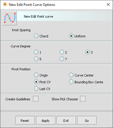
Rather than inputting a curve as CVs we can input it via the Edit Points.
As for CV Curves we should always use Uniform knots. The simplest curve we can create is a two point curve. This is very like the 2 Point Curve Segment in ICEM Surf. The number of CVs we get will depend on the degree we select. I mainly use Edit Point Curves when I’m trying to create a blend between two curves with G2 continuity. In which case I set the degree to 5, specify the two end points and then align the curve to the parent curves.
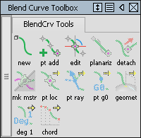
I used to use Blend Curves a lot for creating blend curves - surprisingly! Nowadays I use Edit Point curves instead. Blend Curves are in a different menu system and work very differently to normal curves. They have the advantage of having history - but we can achieve a similar result with Edit Point curves. | |
Before we create a Blend Curve we should first of all make sure that CVs, hulls and Edit Points are shown for new Blend Curves. | |
As for the other curve types the knot spacing should always be Uniform. The most common settings are degree 5 with G2. For Blend Curves there is no need to use Ctrl+Alt to slide along the parent curves. |
To move a Blend Point you pick Edit [IN THE TOOLBOX] then pick the Blend Point and then drag it along the curve. Sometimes the continuity is only G0 in which case you will have to respecify it [TOOLBOX]. If you want G3 continuity instead then you’ll want the degree to be 7 - otherwise it’ll give you a degree 5 2 span curve. You have to select the curve and then use the function in the Toolbox to change the degree. Using the Control Panel or Alt+D will delete the history. Then you can pick the Blend Points [DRAG WINDOW] and apply G3 continuity.
To modify the shape of the Blend you can drag the box to move the 2nd, 3rd and 4th CVs relative to the selected end. The 1st circle moves only the 3rd & 4th CVs. The 2nd circle only moves the 4th CV.
The problem with Blend Curves is that they don’t always want to go in the direction that you want them to.
When we look at matching curves together using a function called Align I’ll show you an alternative way of getting a similar result to Blend Curves but with Edit Point curves.
We’ve already seen some of the Keypoint Curves in relation to circles and arcs. The characteristics of Keypoint Curves include Guidelines which are generated and can be picked up when creating other objects. I’ve never used these and so I switch them off [WINDOW DISPLAY SHOW]. Keypoint Curves can be modified via the Keypoints by using Drag. [IN TOOLBOX] If you move any of CVs instead then the curves will become normal curves.
Another function that can be useful here is the Rectangle. If you create a rectangle you can then easily resize it using the Information Window. The Attributes tab shows the size of the rectangle which is then very easy to edit.
There are a number of other functions to do with lines and circles that may be of use. Personally I’ve never used them.
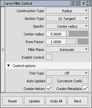
Curve Fillets are the equivalent of the SCorner in ICEM.
To create a fillet pick the 2 parent curves, press Build or, more conveniently, press the Space Bar.
As for all functions you should pretty much always have Auto Update on.
The two dots on the curves tell the function which quadrant that you want the fillet in. To resize the fillet we use the sliders. If you reach the end of the slider then you can use Alt over the number to increase the radius further or you can type in values.
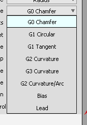
Construction type can be Radius or Chord. With Chord the length can either be the Chordal length or the Tangent length - in other words the distance from the intersect to the fillet end. Continuity can be G0 up to G3. There is also an option for G2 Curvature / Arc which approximates an arc at the centre with lead-in to the parent curves.
If you want to get rid of the result completely then Undo All.
You can change the degree and spans through the Control Panel or use Alt+D.
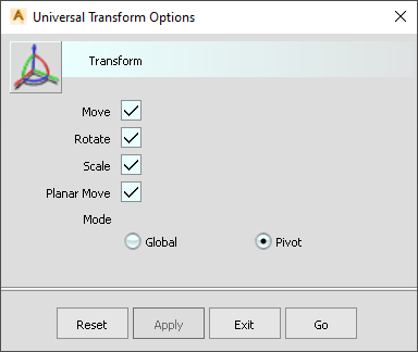
You can Pick CVs and then move CVs using the Transform tools. I often use Move but the Universal Transform tool is another good function. The Manipulator is fairly self-explanatory if you want to move CVs in the X, Y or Z directions. It’s also useful if you want to move a CV parallel to the planes - just pick on the relevant square symbol.
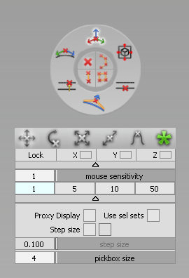
The MoveCV function is specifically designed to move CVs around. This means CVs on curves and surfaces. This is just like the Control Point modification menu in Unified Modelling.
It’s accessed by clicking on the MoveCV icon and then pressing and holding the Space Bar.
XYZ - moves in X, Y and Z of current axis system. For now this is World Space. Later on we will see that we can be in an alternative Construction Plane axis system - similar to Work Planes in ICEM Surf.
Slide - slides CVs along the adjacent hulls.
Projected - projects the CVs onto the chosen Plane, vector or hull. This is one way of projecting a curve onto a Plane. With hulls Projected only works if the curve is degree 2 or more.
NUV - MB1 moves CVs normal to the curve or surface. MB2 moves the CV parallel to the local tangent of the curve.
Parallel - like Projected this needs a Plane, vector or hull. The CVs move parallel to the chosen object.
View - the movements are parallel to the current view. I’ve never used this as I find XYZ far more controllable. It may have a use that I’ve not thought of yet.
Single CV - you can pick one CV. If you want more then either pick the CVs using a window BEFORE accessing MoveCV or use Shift to pick extra CVs.
Hull - pick the whole hull. This is more relevant for surfaces than curves. It’s equivalent to Row in ICEM Surf.
Two CVs - picking the hull line between two CVs picks the adjacent CVs.
Rectangle - this is similar except for surfaces. 4 CVs will get picked.
Move, Rotate, Scale and Non-proportional Scale are all fairly obvious. The Pivot point is going to be significant for the Rotate and Scaling options. You can move the Pivot using the Pivot icon.
PMod - is similar to the Law function in Unified Modelling where we can get a blended change. You can choose the number of CVs affected and the type of blend.
Lock X Y Z - is similar to locking the X Y and Z in ICEM Surf’s Control Point menus. In Alias I’ve never ever had to use this as you can use the mouse buttons to do the same thing.
Proxy display - shows the original curve.
Step Size - is like Delta in the ICEM Surf Control Point menus. If you specify a distance and lock the padlock then you can only move the CVs by picking in space. Remember in a view that you can use the MB2 to move left to right and the MB3 to move up and down. If you try and drag the mouse then nothing happens. If you want to be able to drag the CVs as well then switch off the padlock. Picking locations on the screen will still allow you to move in increments. When you drag though the CV movements are not constrained.
Pick Box Size - this defines the search area around the cursor when you’re picking CVs. If you find it difficult to pick CVs it may be that you need to increase this size. I usually have it set to 20. It’s a pixel size, not mms.
Use Selection Sets is probably not very applicable to curves. It’s more relevant to Surfaces and SubD.
Stretch is similar to the Reference option in the ICEM Surf Curve Control Point menu except that we don’t need to specify a reference object. We can just stretch the curve using the handles. You can add handles. You can move the handles along the curve. Usually you would want two handles at the ends of the curve.
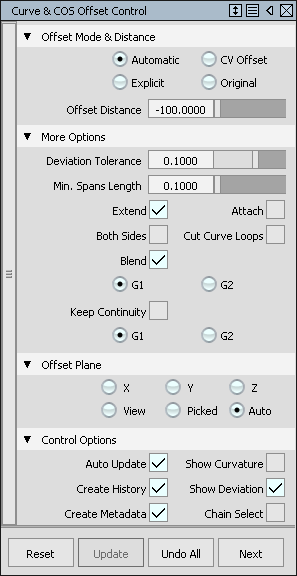
Automatic tries to get the most accurate result, but it does this by increasing the number of spans. CV Offset is the best from the point of view of CV patterns. Explicit gives you control over the degree and spans. Original uses the parameterisation of the original curve.
As we always want the best patterns of CVs and complete control over the degree and spans then I would choose CV Offset nearly always. If the result is not accurate enough then increase the degree of the original curve. History means that the offset curve updates so you can see exactly what the deviation is. Deviation between curves is found under the Locators tab. Once you’ve finished you can delete all the Locators using MB2 with the Marking Menu.
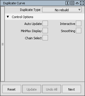
Duplicate has a number of ways of reapproximating curves all of which I’ve never used in a real job. I’ll either just change the degree or spans in the Control Panel or build a new curve from scratch starting with a straight line Edit Point curve.
The most important use of Duplicate is if you need a curve on the edge of a surface or as an approximation of a Curve On Surface (COS). In this case we would use the No Rebuild option. In the case of a surface edge the curve will be exactly the same as the edge. This is the same as if you picked a patch edge in ICEM Surf using Curve Control Point.
In the case of a COS the curve will be an approximation of the COS.
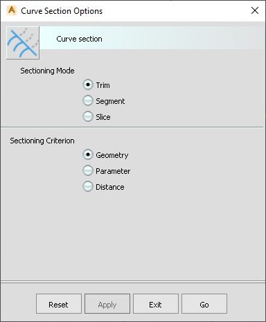
If you want to trim curves to each other you would use Curve Section with Trim & Geometry on.
Segment is the same but keeps both parts of the curve. Segment Parameter lets you divide a curve into smaller and smaller segments, a bit like Curve Segment Trim Segment in ICEM Surf.
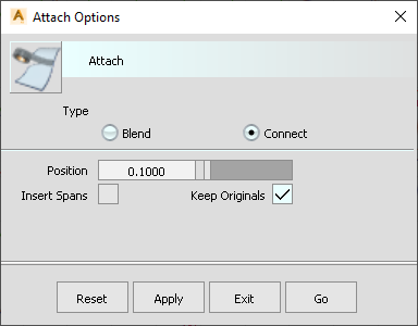
Attach tries to join two curves together. This can only ever be an approximation of the original. For that reason I rarely use it. I would rather just build a new curve over the top of the old ones and modify it until it was close enough. If you do want to use it then the best results come from using Connect. Don’t add any spans and Keep Originals so that we can compare the final result. If we’re joining two curves together then it will create a 4 span curve. What it does is add 2 zero length spans at the connection point. In other words we have a multi-knot. Multi-knots are not good as they reduce the continuity at this point. If you pull the centre CV you’ll see that this is not a good result as we’ve now only got G0 at this point. So we have to first increase the degree and then reduce the spans to 1 - assuming that we want a Bezier curve. We’ll then need to check the accuracy back to the original curve.
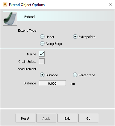
Extend is very much like Extrapolate in ICEM Surf except that it has some extra features. Extrapolate with Merge is the same as Extrapolate in ICEM. If you tick Merge off then you get a separate curve. I find that Linear with No Merge is particularly useful as it gives you a tangent line off the curve end.
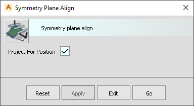
Alias was designed with the car industry in mind from the start, so naturally, the default symmetry plane is XZ. There are two ways in which we can implement symmetry in Alias. The first one we’ll look at is SymAlign. This is just like the Centreline Symmetry function in ICEM Surf. If we go to FRONT view and then throw a curve in. It doesn’t need to start exactly on the Y0 plane - just somewhere near will do. You’ll generally want Project for Position on so that the end CV gets projected onto Y0. The function puts history on the curve so you can freely move the CVs around to get the shape right without worrying about symmetry all the time. The only thing that you have to be careful of is that the centre point is not fixed to Y0 - so only use MB3 to move this up and down.
Of course with a half-model we always have the problem of trying to get G3 across the centre line. It’s certainly quicker with history on but a better way is to use the Symmetry function. this needs a curve that sits astride the Y0 plane. We don’t need to worry about an accurate curve - just throw an Edit Curve with degree 5, say, in. When we apply Symmetry it makes the curve completely symmetric, again with History on. If you don’t like the result then you can Flip Master Side to get a different result. Now we can move the CVs around completely freely as symmetry - including G3 - is maintained at all times. In ICEM Surf there is an equivalent function in Unified Modelling.
I find creating a full width model is quicker and certainly gives a better quality result over the centre line. When it comes to surfacing it’s only the blocks that need to be full-width. You do have to commit to making them all full-width. Once they’re complete then you can Trim (Face) them all at Y0 to create a half-model. The fillets can be just done on one side and then the whole model mirrored.
Suppose you have started a model as a half-model and then decided to make it a full model instead. Rather than starting again you may be able to mirror the curves across, reapproximate them using Duplicate as we talked about before and then applying Symmetry to make sure that they are symmetric.
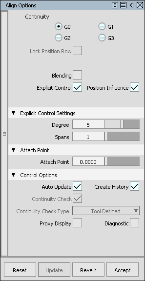
Align is the equivalent of ICEM Surf’s Matching functions. In Alias Align is used for curves and surfaces. At the moment we’re just going to look at curves of course. As always we want Auto Update on. We’ll also put History on. There are times with Surfaces that we don’t want History on but we’ll discuss that later. Explicit Control means that we can modify the degree and spans in the menu if we wanted to. All we have to do is pick the curve that we want to modify and then the one that we want to align it to, exactly the same as in ICEM Surf.
Unlike ICEM Surf there is no Project option. You can move the end point up and down the curve to wherever you want it. If you want to make sure it’s at the end then check the arrow. If there’s only one arrow head then it’s at the end, otherwise it’s not. If in doubt just drag it there.
Because of History we can change the parent curve and see the aligned curve update. We can pull the CVs around on the aligned curve. We can change the continuity at any time.
If you want to create a blended change then you can use Blending. The Extra CV Rows are the number of CVs that you want to affect in addition to the ones being affected by the continuity. In this way you can ensure that the continuity at the other end of the curve isn’t lost.
Rather than using Blend Curves for G2 blends I now use Edit Point curves of degree 5, G2 Align them with History on and then pull and push them around using the CVs until I get the result I need. One of the benefits over Blend Curves is that you can get the end tangents pointing in whichever direction you want, plus there’s no having to think about a different set of functions as in the Blend Curve Toolbox.
Proxy Display shows the original curve.
To line up all of the CVs with the same X Y or Z value we can select them and then constraining their movement with the appropriate mouse button we can pick a location which has the X Y or Z value that we want.
You can also use the Information Window to edit values using Copy and Paste.
MoveCV with Parallel is a way of projecting the CVs onto a Plane.
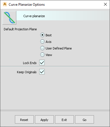
If you want the CVs to all lie on a plane then use Curve Planarize. Best just projects the curve onto a best fit plane. I’ve never used this. I usually prefer to set up a plane instead rather than relying on chance. Axis is good for projecting the curve onto XY, YZ or XZ. User Defined Plane does a similar thing without having to go into the Plane. View puts all of the CVs onto an imaginary straight line between the end points.
Surface maths is just an extension of curve maths but in 2 directions. As for ICEM Surf these are the u and v directions. Iso-curves in ICEM are called isoparms in Alias. I tend to call the knot isoparms knot-lines just to try and make it clear what we’re talking about. Surfaces are controlled by CVs, just like curves. The lines connecting the CVs - the rows in ICEM Surf - are called hulls in Alias.
Just like curves, surfaces can be Rational. Again this is not recommended. If you’ve switched off the Rational flags in the Construction Settings then this won’t be a problem.
Before we start to look at surface creation it makes sense to look at surface trimming in Alias. This is where the terminology is the most confusing if you’re coming from ICEM Surf.
In Alias a Trimmed Surface is the equivalent of a Face in ICEM Surf. To Trim / Face a surface we first of all have to create Curves on Surface by projecting curves or intersecting another surface or by creating a Curve on Surface directly - although this is not often done. Curves on Surface are a completely different type of entity to curves. They are embedded in the surface. If you want to pick them then you have to Pick COS. If you wanted to create a curve copy of a COS then you would use Curve Edit Duplicate with No Rebuild. Curves on Surface are degree 3 multi-span entities as you can see if you look in the Information Window.
The beauty of Curves on Surfaces is that you can retain them for future use. For example if you had two intersecting surfaces you could create a COS at the intersect. When you fillet the surface you can generate COSs at the edges of the fillet so that the blocks can be Trimmed. At any time we can Untrim the surfaces and retrieve the intersect and fillet rail Curves on Surface easily. What you have to watch out for though is leaving unwanted Curves on Surface embedded in the Surface.
What ICEM Surf calls Trimming is known as Trim Convert in Alias. This is a two step process. Firstly we need a Trimmed Surface - or Face in ICEM speak. Then we convert it to a 4 sided Trim Converted Surface. Just as in ICEM Surf this is usually an approximation of the original surface.
To split a Surface in two along its Isoparms we can use Detach. This is similar to Surface Trim Isocurve Duplicate.
If instead we wanted to Trim a surface to an isoparm in Alias then we could use Insert to create a Curve on Surface. Then we can Trim the Surface.
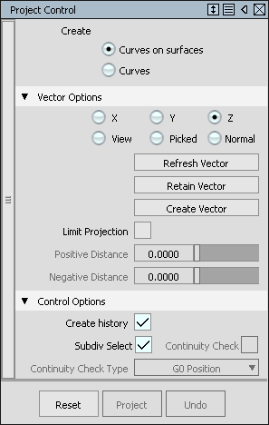
To project a curve onto a surface and create a Curve on Surface we use Surface Edit Project. We can also create a Curve this way but of course we won’t be able to Trim a surface to this.
The Vector Options work in the same way as the ones we’ve seen before. If you don’t want to project curves on surfaces outside a certain range then you can use Limit Projection.
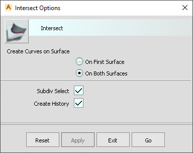
Surface Edit Intersect creates intersects. If you want to Trim both surfaces then you’ll need a Curve on Surface on BOTH surfaces. If Create History is on then the intersects will update even if the surfaces change.
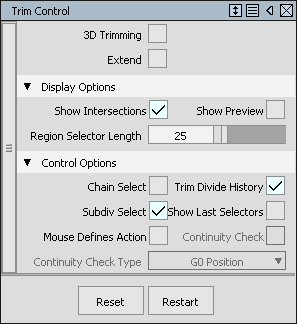
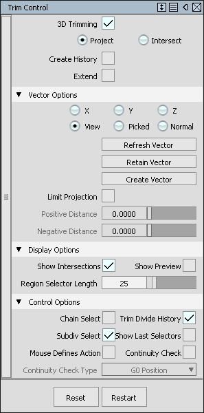
If you already have Curves on Surfaces on the surface then you can use Trim Surface to select the regions that you want to keep. There is the choice of Keep, Discard or Divide.
If you switch on 3D Trimming then you can create Curves on Surface within the menu using Project or Intersect. If it’s a simple case then this is more efficient than Projecting or Intersecting separately. Extend is useful if the Curves on Surface don’t quite reach the edge. The edges that need extending are highlighted in pink. You can either pick on them or use Automatic with a large enough tolerance.
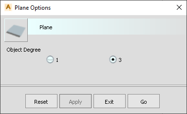
The simplest surface that we can create is a planar square using the Surface Plane function. If you just need a flat surface then use degree 1. If you’re going to modify it then use degree 3. Of course you might have to change this anyway using Alt+D.
The surface is created from a single centre point.
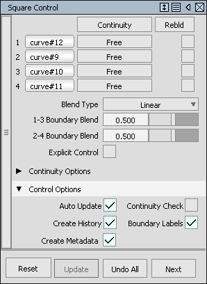
Square does not create a square! It creates a 4-sided surface. It’s similar to Patch Create 4Pts and Patch Create Curves in ICEM Surf.
If you want to create a surface from 4 corner points then you have to pick on geometry or grid points - you can’t just pick anywhere.
Alternatively you can pick 4 curves or surface edges - as long as they touch or intersect then Square will create a surface. If you find that it refuses to create a surface then the usual cause is that the curves are not within tolerance. Obviously for A-class the best thing that you can do is to fix the curves. But if you’re roughing things in quickly and don’t care about the accuracy then the alternative is to increase the tolerance. This is the Curve Fit Distance in the Construction Settings.
You can combine point picks with curves as well.
You can set continuity to various levels from G0 to G2. Free means that position is ignored if the continuity of other edges demands it. Rebuild means that the parameterisation of this edge is copied from the other side.
Under Continuity Options you can specify whether the surface is aligned linearly when you’ve picked surface edges.
G1 Implied and G2 Implied both result in an edge that is tanned into the symmetry plane of the current Layer. The curves must be G1 across the symmetry plane for this to work.
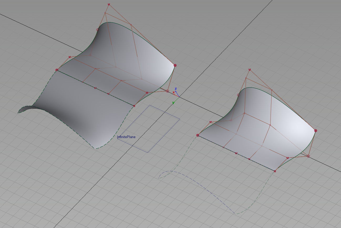
In this example the left hand surface uses Implied Curvature on the symmetry plane edge, the right hand surface uses Implied Tangent. The curves are the same in both cases. In other words the 2nd and 3rd hulls are interpolated from the end curves. This is NOT like SymAlign. The tangency at the symmetry plane is NOT being controlled here directly.
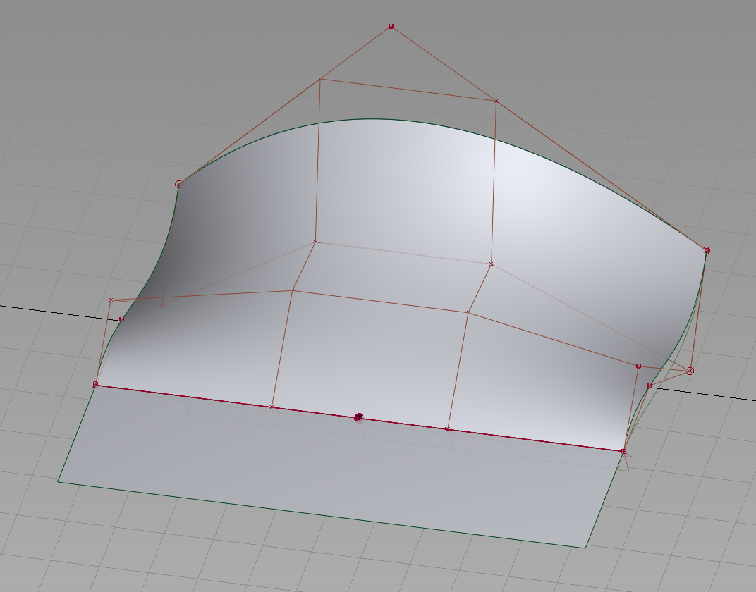
Here are the same curves with Tangent Angle on the symmetry plane. The adjacent edges are Free. The angle of the surface relative to the draft surface can be controlled by the manipulator.
Rail is similar to Profile in ICEM Surf.
Generation Curves are equivalent to Profiles in ICEM Surf. Rail Curves are equivalent to the ICEM Surf Spine Curve.
We have to specify the number of Generation Curves and Rail Curves before we pick any geometry.
The simplest possibility is when we have 1 Generation Curve and 1 Rail Curve. Notice that the icon and menu title changes. Although the two curves don’t need to touch I always think it’s so much easier if they do. I always set up the profile curve to be exactly where I want it. It’s just more intuitive that way.
The most important Sweep modes are Natural which is like ICEM Surf’s Radial to Spine Curve option and Parallel which is equivalent to ICEM Surf’s Parallel to Plane.
Rotate and Scale can be used to modify the profile as it sweeps along the Rail. Curve Segments can be used to limit the extent of the Rail. I never use any of these options because they’re not as controllable as actually building the curves that you want first.
If I wanted to twist or scale the surface I would firstly create a Monorail. Then Duplicate the far end as a curve. Then I would scale or rotate this curve and finally create a new, 2 Generation Curve Rail Surface. With History on I can then modify the curves even further if necessary.
The other possibility is to modify the second profile curve and then Align the Surface to it with Blend on.
In the unlikely event that you wanted a Rail Surface with more than 2 Generation Curves then pick 2+. Watch the User Prompt as the pick sequence is then slightly different.
2 Rail Curves is like the 2nd Curve option in ICEM Surf’s Profile function. If you want to maintain the profile shape then use the Scale option. If you want to stretch the profile as it runs along the Rail then use Non-Proportional Scale. If you want to rotate the profile but not scale it then you can choose Rotate No-trim. If it fails to work it’s most likely because the Profile Curve is not long enough. The beauty of having History on is that you can extend the profile until it does work.
Profile is not available in Alias Concept. It’s similar to Rail Surface in some ways but has many more advanced options.
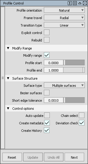
The most common choice of Profile Orientation is Natural - just like Normal to Spine in ICEM Surf. The other common choice is with Frame Travel set to Parallel - just like Parallel in the ICEM Surf Profile function.
Unlike Rail we don’t need to specify how many profiles we’re going to create before we start. As a result the picking is slightly different.
The other difference is that we can pick multiple curves to define each profile. The rail can also be built from several curves. Once we’ve picked a Profile then we pick the Space Bar. We repeat this for every Profile. Once we’ve picked them all then we pick the Space Bar again so that we can now pick the Rail Curves. Once we’ve picked those then we click the Space Bar once more to complete.
If your profiles and rails do consist of several curves then Chain Select can be great as you only need one pick for the system to find all of the curves in each set.
Single Surface results in a single multi-span surface. Multiple Surfaces with Bezier on results in all Bezier surfaces.
Rotate to Target uses a curve or surface as the Profile Target. In the case of a curve using Profile Point means that the profile will be scaled to the 2nd curve - just like in Rail when we have 2 Generation Curves. Otherwise it’ll just rotate the profile until it touches the 2nd curve. With Surfaces and Profile Point on, the profile rotates until the end touches the target surface. With Profile Point off the profile will rotate until it tans into the surface - if it can. It will fail if this is not possible. Either extend the curve or modify its shape. Free Curve creates a curve at the touch point.
Slide to Target is very clever - although I’ve yet to find a use for it.
Guide Curve is just like having a 2nd curve in Rail Surface. You can choose whether the scale or stretch or simply rotate the profile.
Surface Normal is pretty much the same as Normal to Surface in the ICEM Surf Profile command.
These are intended mainly for CAS work. They can create a blend surface between multiple edges but the results are not likely to be suitable for A-class. However they are good if you want a blend between just two edges because the CVs on the blend surface are then matched to the parent surfaces.
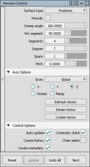
Revolve is the Alias equivalent of ICEM Surf’s Surface of Revolution. As for circles, to get an accurate result we need to always set Segments to 4, Degree to 7 and Spans to 1. For small geometry you may be able to get away with 2 segments and a lower degree - but check that it’s within tolerance by looking at the max and min values of radius.
Global refers to the current Construction Plane. Local refers to the Pivot Point of the profile curves.
if at any time the surface doesn’t update then click on Refresh Vector or switch Auto Update off and on.
There is also a manipulator [MANIP] which you can use to adjust the axis position.
Picked means that you can pick a Vector for the axis.
If you ever wanted to create a spring - unlikely for A-class I know, but it is fun! - then it’s easy with Revolve. Set the Sweep Angle to the number of coils times 360. For example if you wanted 10 coils then the Sweep Angle would be 3600. The Pitch determines the stretch of the spring.
Another use of Revolve is in creating a side glass from scan. The first option is for a Barrel shape. The first 3 points define a cross-section. The function automatically picks up on the scan data. The next 2 points determine the extent of the glass in the -ve and +ve X directions. You can play with the points to try and get the best fit to the scan.
With the Helix option we need to pick a curve first. Then a point near the top of the glass and one at the bottom. We can then adjust the Pitch to try and get the best fit to the data.
There are a number of Flange functions, similar to some of the functionality in ICEM Surf.
Fillet Flange is the first. Show Wall is helpful as it shows how the fillet is being constructed. For instance if we have Normal on then the Wall surface is normal to the parent surface. If it’s Draft and Y then you’ll see that the Wall surface is horizontal. Sweep angle is measured relative to the parent surface. Length is the length of the flange from the edge of the fillet.
Tube Flange is similar except that the fillet grows from the picked edge rather than a theoretical Wall surface being created first.
Tubular Offset creates a tube, a groove or just offset Curves on Surface. Notice that the tube is only 1 surface and is therefore not 100% accurate in terms of circularity. If you wanted more accuracy then Profile, Normal to Surface is a better option.
Panel Gap creates two flanges and two fillets with a specified gap. The only input required is a single Curve on Surface which can be at the centre of the gap or to one side.
The flanges are created relative to the patch normal. This is the Sweep Angle option. The other option is to create them relative to the tool direction.
The Gap Distance is defined as the functional gap in other words the gap that would be physically measured with a carrot gauge.
You can pick a single surface or you can pick two surfaces with underflush.
The flange length is measured from the fillet edge to the edge of the flange.
As for ICEM Surf there will be times when the function doesn’t give a good result because of the nature of the block surfaces in which case you will have to manually build these areas.
MSDraft is similar to Flanges in ICEM Surf. There are two modes in MSDraft; Draft and Normal. Draft uses a direction such as Y, Normal creates a surface normal to a parent surface.
With Draft on then the Draft Angle is relative to the chosen direction - the Vector Options. These can be X, Y or Z in the current axis system. View is normal to the view - in other words the draft direction is pointing into or out of the screen. Picked allows you to select a Vector. Manip lets you create more manipulators on the curves - which is good if you want to add a twist or a variable length to the draft surface.
If you want to keep the current vector direction then use Retain. Create Vector lets you - create a vector.
Flip Surface will flip the surface in the opposite direction. If the Draft Angle is not zero then you can use Flip Angle to choose the direction that you want. If you have selected a surface edge then Length Mode of Default means that the Length is measured along the draft surface. Projected means that the far edge of the draft surface will be this distance from the parent surface.
There are two fillet functions in Alias: Surface Fillet - which is very much like the ICEM Surf Fillet function and Symmetric Fillet which is like the Curve function inside ICEM Surf’s Fillet command.
This is similar to the Fillet Surface in ICEM Surf with the Radius and Chord options. Normally I’ve said to switch on Auto Update at all times, but filleting can take some time to update, depending on the complexity of the surfaces, so it’s often better to switch off Auto Update in the Fillet functions.
Flow Control determines the nature of the ends. Default gives the shortest fillet - just like the default in ICEM Surf. Extend extends the fillet - just like ICEM Surf. Edge Align is like ICEM’s Extend with Matching. Connect does a similar thing but the cut of the fillets ends is planar instead.
Just as in ICEM Surf Extend and Edge Align can sometimes result in poor quality CVs towards the fillet end and a higher number of spans. It can be better to use Default and then extend the fillet outside of the fillet function.
Section Types can be:
G0 Chamfer you would usually want to add Crown to. Proportional adds Crown based on the Chordal distance. For instance a Proportional Value of 0.5 adds half the Chordal distance as the Crown amount. Absolute adds a specific mm amount of crown. Crown Flip reverses the crown direction.
G1 Circular is the best option if you want an accurate circular section.
If you want a fillet that is tangent based and as simple as possible then use Lead. This gives you a G1 degree 3 fillet with a Knee Ratio which controls the amount of lead-in. G1 Tangent is similar but the default degree is 5.
G2 Curvature results in a degree 5 surface, much like in ICEM Surf. G3 Curvature gives you a degree 7 surface with G3 continuity at the edges. Both have a Form Factor - similar to ICEM Surf.
G2 Curvature / Arc creates a fillet with an approximately circular centre section, with G2 continuity to the blocks. This is much more complex understandably - it’s degree 5 with 3 spans.
Bias creates a fillet which is biased towards one side or the other.
Personally I don’t feel a need for either G2 Curvature / Arc or Bias.
This is similar to the Curve option in Fillet Surface in ICEM Surf.
Mesh
MB1 toggles locator on and off. Also scales comb.
MB2 toggles comb and adjusts samples.
MB3 displays information about the continuity.
You can also use the Information Windows to modify the settings.
Can’t select something – check whether you’re locked into the User Prompt. If so, Tab away
Object is not updating when I change parameters or the driving curves – you’ve not got Auto Update on.
Trying to draw a curve but it’s just creating a straight line – you’re in perspective not orthographic view – or you’re not quite in LEFT view for instance. The grid will show when you are.
ICEM Surf | ALIAS |
MoveCV: Mouse Sensitivity | CtrlP: Mouse Warp |
Materials | Shaders |
ICEM Surf | ALIAS |
Flange | Surface - MSDraft |
CtrlPt | Control Panel - MoveCV |